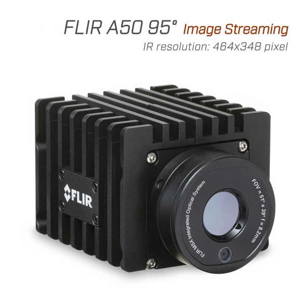
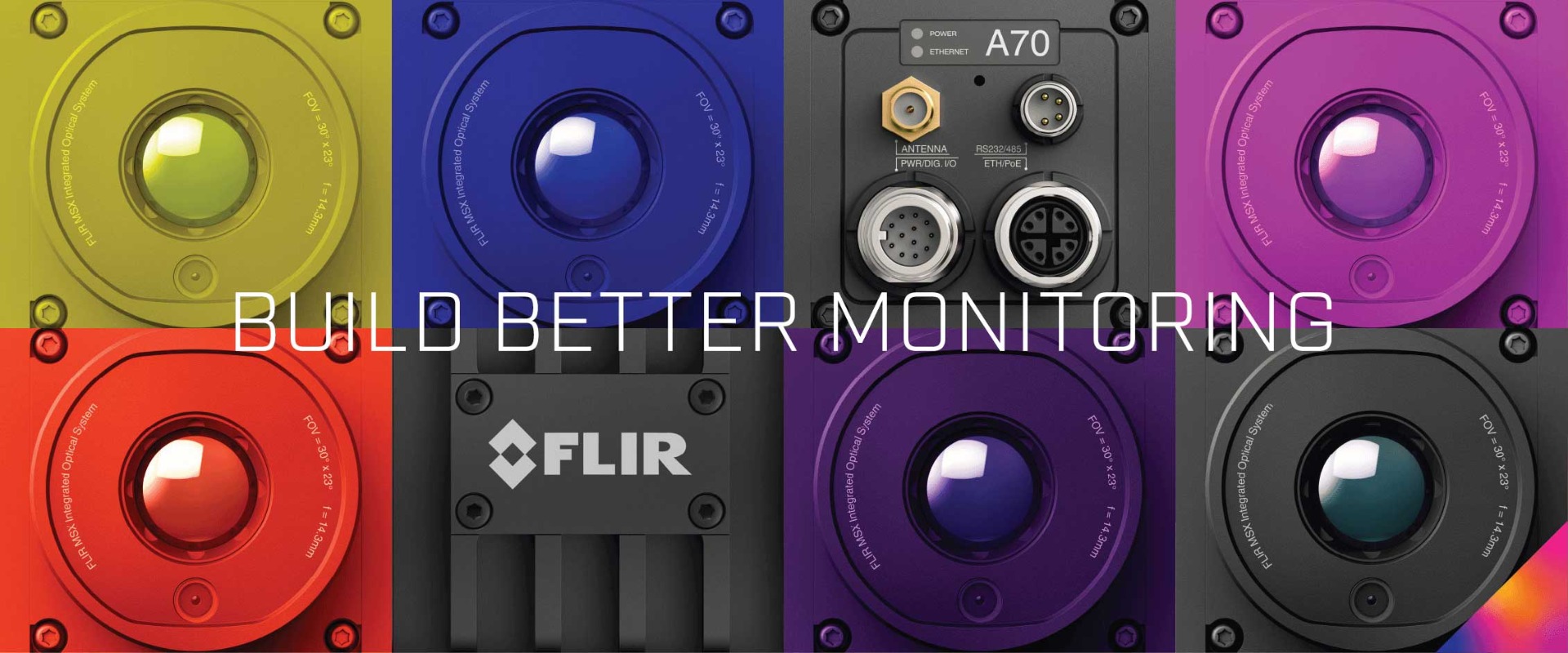
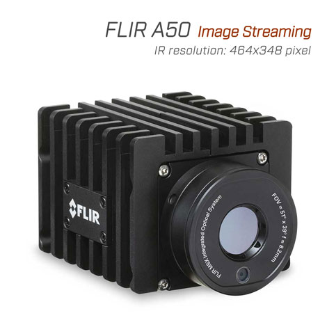
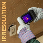
FLIR A50 และ A70 คือกล้องถ่ายภาพความร้อนแบบติดตั้ง ที่สามารถใช้สำหรับการใช้งานที่หลากหลายรวมถึงการคัดกรองอุณหภูมิสูงเป็นส่วนเสริมกับเครื่องมือคัดกรองอุณหภูมิร่างกายอื่น ๆ การตรวจสอบโครงสร้างพื้นฐานที่สำคัญการประเมินคุณภาพของผลิตภัณฑ์หรือการตรวจจับสัญญาณความร้อนสะสม
กล้องถ่ายภาพความร้อนแบบติดตั้ง FLIR A50 ให้ภาพอินฟราเรดคุณภาพสูง 161,472 พิกเซล (464x348) เหมาะสำหรับการตรวจสอบหรือติดตามการเปลี่ยนแปลงของอุณหภูมิ สามารถดูค่าอุณหภูมิจุดใดก็ได้ในฉาก ออกแบบมาให้สามารถติดตั้งได้เกือบทุกที่เพื่อตรวจสอบอุปกรณ์ที่สำคัญของคุณ จะช่วยให้เห็นปัญหาก่อนที่จะเกิดความเสียหาย เป็นการป้องกัน และสั่งหยุดทำงาน เพื่อเพิ่มความปลอดภัยของผู้ปฏิบัติงาน
เหมาะสำหรับลูกค้าที่ต้องการสามารถในการควบคุมกล้องและการสตรีมภาพผ่านอินเตอร์เน็ต รวมถึงความยืดหยุ่นในการวิเคราะห์และรวบรวมข้อมูลดิบของภาพถ่ายความร้อนด้วยแอพพลิเคชั่นหรือโปรแกรมของตัวเอง นอกจากนี้ตัวกล้องยังสามารถปรับแต่งให้เหมาะสมกับงานรูปแบบต่าง ๆ ในระบบอุตสาหกรรม ไม่ว่าจะเป็น build-in Wi-Fi รวมเข้ากับตัวกล้องในการสตรีมภาพ หรือรองรับ ONVIF S (Advanced) ทำให้ตัวกล้องมีขนาดเล็กกะทัดรัดและน้ำหนักเบา และยังช่วยเพิ่มประสิทธิภาพในการควบคุมการผลิตได้เป็นอย่างดี
Overview
Base Mounting
4 x M2.5 direct into camera or 4x 10-32 UNF onto bottom cooling plate
Encoding
RTSP video streaming: H.264 / MPEG4 / MJPEG
RTSP radiometric streaming: compressed JPEG-LS, FLIR radiometric
GVSP video streaming: uncompressed
GVSP radiometric streaming: temperature linear and FLIR radiometric
Housing material
Aluminium
ONVIF Profile S Compliant
Yes
Size (L x W x H)
107 × 67 × 57 mm (4.21 × 2.64 × 2.24 in)
Weight
519g (1.14lb) without bottom cooling plate
Connections & Communications
Digital I/O connector type
M12 12-pin A-coded, Male (shared with external power)
Digital I/O isolation voltage
500 VRMS
Digital input purpose
NUC; NUC disable; image TAG (Start, Stop, General); image flow control (acc. SFNC 2.3):
• Single frame (on trigg)
• Multiframe (on trigg)
• Continuous
Digital Inputs
2x opto-isolated, Vin(low)= 0–1.5 V, Vin(high)= 3–25 V
Digital Output Purpose
Programmatically set; fault (NC)
Digital Outputs
3x opto-isolated, 0–48 V DC, max. 350 mA; solid-state opto relay; 1x dedicated as Fault output (NC)
Ethernet
For control, result, image, and power
Ethernet Communication
• GigE Vision ver. 1.2
• Client API GenICam compliant
• TCP/IP socket-based FLIR proprietary
Ethernet Connector Type
M12 8-pin X-coded, female; RP-SMA, female
Ethernet Interface
Wired, Wi-Fi (optional)
Ethernet Power
Power over Ethernet, PoE IEEE 802.3af class 3
Ethernet Protocols
• IEEE 1588
• SNMP
• TCP, UDP, SNTP, RTSP, RTP, HTTP, HTTPS, ICMP, IGMP, sftp (server), FTP (client), SMTP, DHCP, MDNS (Bonjour), uPnP, GVSP, GVCP
Ethernet Standard
IEEE 802.3
RS-232
M8 A-coded, male connector
Serial Communication
Pan & Tilt control. Pelco D standard
HW interface: RS232 and RS485 exclusively
WiFi
Optional feature purchased separately. RP-SMA, female connector
Environmental
Atmospheric transmission correction
Based on inputs of distance, atmospheric temperature, and relative humidity
Corrosion
• ISO 12944 C4 G or H
• EN60068-2-11
EMC
• ETSI EN 301 489-1 (radio)
• ETSI EN 301 489-17 (radio)
• EN 61000-4-8 (magnetic field)
• FCC 47 CFR Part 15 Class B (emission US)
• ISO 13766-1 (EMC - Earth-moving and building construction machinery)
• EN ISO 14982 (EMC - Agricultural and forestry machinery)
Encapsulation
IEC 60529 and IP66
Humidity (Operating and Storage)
IEC 60068-2-30/24 hours, 95% relative humidity, 25–40°C (77–104°F)/2 cycles
EN60068-2-38
Operating Temperature Range
–20 to 50°C (–4 to 122°F)
Bottom cooling plate is needed in temperatures above 40°C (104°F).
Maximum internal temperature sensor: 70°C (158°F)
Radio Spectrum
• FCC 47 CFR Part 15 Class C (2.4 GHz band US)
• FCC 47 CFR Part 15 Class E (5 GHz band US)
• RSS-247 (2.4 GHz and 5 GHz band Canada)
• ETSI EN 300 328 V2.1.1 (2.4 GHz band EU)
• ETSI EN 301 893 V2.1.1 (5 GHz band EU)
Shock
IEC 60068-2-27, 25 g
Tripod Mounting
4 x M2.5 direct into camera or 4x 10-32 UNF onto bottom cooling plate
Vibration
• IEC 60068-2-6, 0.15 mm at 10–58 Hz and 2 g at 58–500 Hz, sinusoidal
• IEC 61373 Cat 1 (Railway)
Imaging & Optical
Contrast Enhancement
FSX® / Histogram equalization (IR only)
Field of view (FOV)
95° × 74°
Focal Length
4.1 mm (0.16 in)
Focal Plane Array (FPA)
Uncooled microbolometer
Focus
Fixed, adjustable with included tool
Minimum Focus Distance
0.1 m (0.33 ft)
MSX
Yes, included in visual camera option
Radiometric IR video streaming
GigE Vision and RTSP
Readout
No measurements readouts, only streamed video
Streaming Resolution
RTSP video streaming, source 0: 640 × 480 pixels
RTSP video streaming, source 1: 1280 × 960 pixels
RTSP radiometric streaming: 464 × 348 pixels
GVSP video streaming: 640 × 480 pixels
GVSP radiometric streaming: 464 × 348 pixels
Thermal Sensitivity/NETD
<45mK
Video Streaming
RTSP or GVSP (GigE Vision) protocols
Visible Camera
Optional accessory
Measurement & Analysis
Accuracy
±2°C (±3.6°F) or ±2% of reading, for ambient temperature 15°C–35°C (59°F–95°F) and object temperature above 0°C (32°F)
Automatic hot & cold detection
NA
Measurement Corrections
NA
Object Temperature Range
–20 to 175°C (–4 to 347°F)
175 to 1000°C (347 to 1832°F)
Power
External Power Operation
24/48 V DC 8 W max
External Voltage
Allowed range 18–56 V DC
Power Connection
M12 12-pin A-coded, male (shared with Digital I/O)
Power Consumption
• 7.5 W at 24 V DC typical
• 7.8 W at 48 V DC typical
• 8.1 W at 48 V PoE typical
Storage Media

